FlowerFriend


A wearable LED flower necklace that lights up when near others.
50 were given away at Burning Man 2015.

Learn More

Concept


FlowerFriend was conceived some time in March, 2015 at a bar in the Haight-Ashbury district of San Francisco. Hundreds of daffodils were being gifted at random to strangers by street kids. It seemed like they had been picked from somewhere in Golden Gate Park. We thought that it would be wonderful to give away a flower that didn't wilt, that encouraged interaction with others, and that could provide a useful function--locating your friends in a crowd and staying visible at night.

The resulting design was a custom circuit board with a color-changing LED, integrated 2.4 GHz radio transceiver, and USB-rechargeable lithium polymer battery. Every board was hand-assembled, hand-soldered, and included a unique fabric flower that was hand-sewn. Upon flipping the power switch to "on," a random color is assigned to each unit. When the units come into within approximately 150 feet of each other, they exchange colors and fade between all colors that have been seen, in sync.

Interaction


Our neighbor was caught in a dust storm alone, unable to see more than a few feet ahead. He looked down at his flower and saw that it was fading between two colors. Though he couldn't see anyone, or figure out where he was, he knew that one of his friends was still nearby and experiencing the same cloud of dust.

A friend was searching for the founder of her camp. Other camp members offered varied stories about where he might be: out in the open playa fixing his art project, at the neighboring camp's party. Before heading out to one of those locations, she switched on her flower. It started pulsing near an RV in the camp. Inside, he was taking a nap!

Keeping a large group together at night can be very difficult. One way to manage a group is to set destinations and keep count of everyone at each stop. With 13 people wearing flowers, a friend reports that everyone stayed together throughout the course of the night.

Circuit Design


Introduction

After some initial prototyping on breadboards with some simple Arduino code, the project quickly became focused on designing and testing custom circuit boards (OSH Park, PCBCart), then figuring out how to manufacture them efficiently and inexpensively. The main challenges were tuning the 
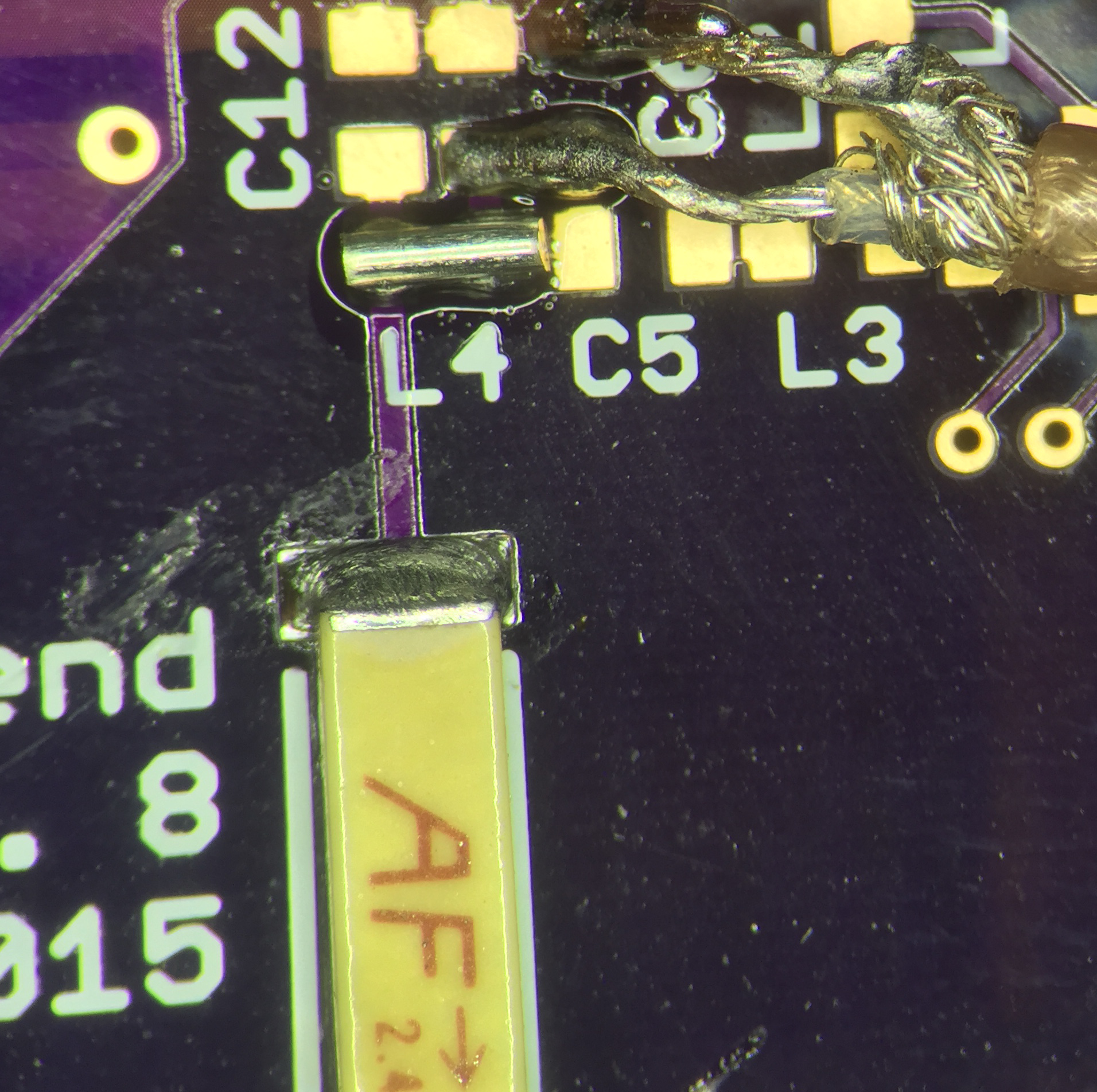
matching network of the NRF24L01+ to maximize range, and consistently hand-assembling the many 0603 sized components and NRF24L01+, which comes in a QFN (pinless) package. It is nearly impossible to use an iron to solder a QFN package without damaging it. Instead, I used the solder paste and stencil (OSH Stencils, Stencils Unlimited) method with baking in a toaster over (Reflowster).
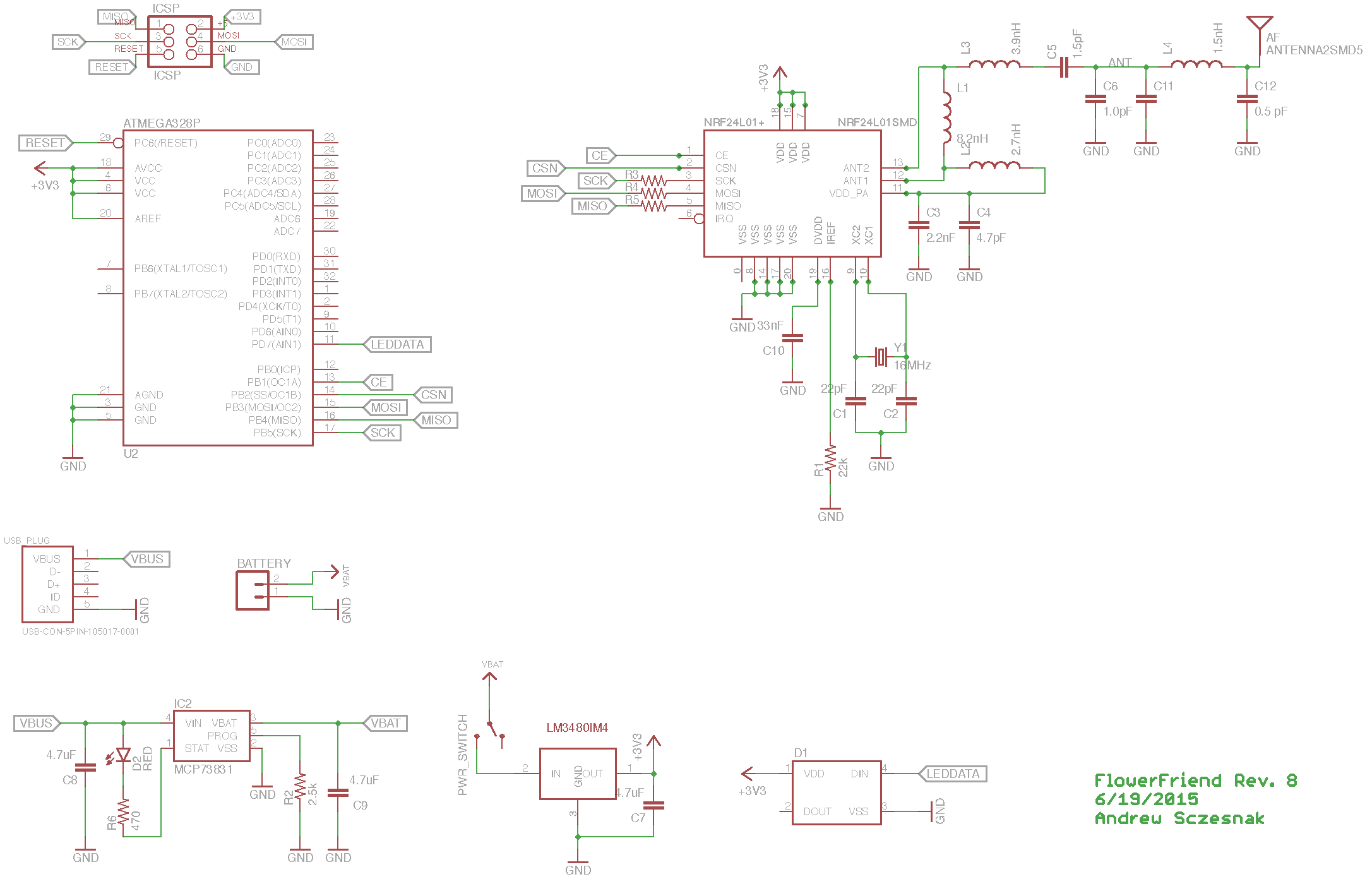


Breadboard prototypes sync wirelessly

Design Overview

Every flower must have the ability to do calculations, transmit and receive RF signals, power a color-changing LED, and recharge its battery over USB. To perform these functions, every flower has these components:

  • Atmel ATmega328P 8-bit microcontroller
  • Nordic NRF24L01+ 2.4GHZ transceiver
  • WS2812B "NeoPixel" SMD5050 RGB LED
  • TI LM3480 3.3V Voltage Regulator
  • MicroChip MCP73831 LiPo Charger
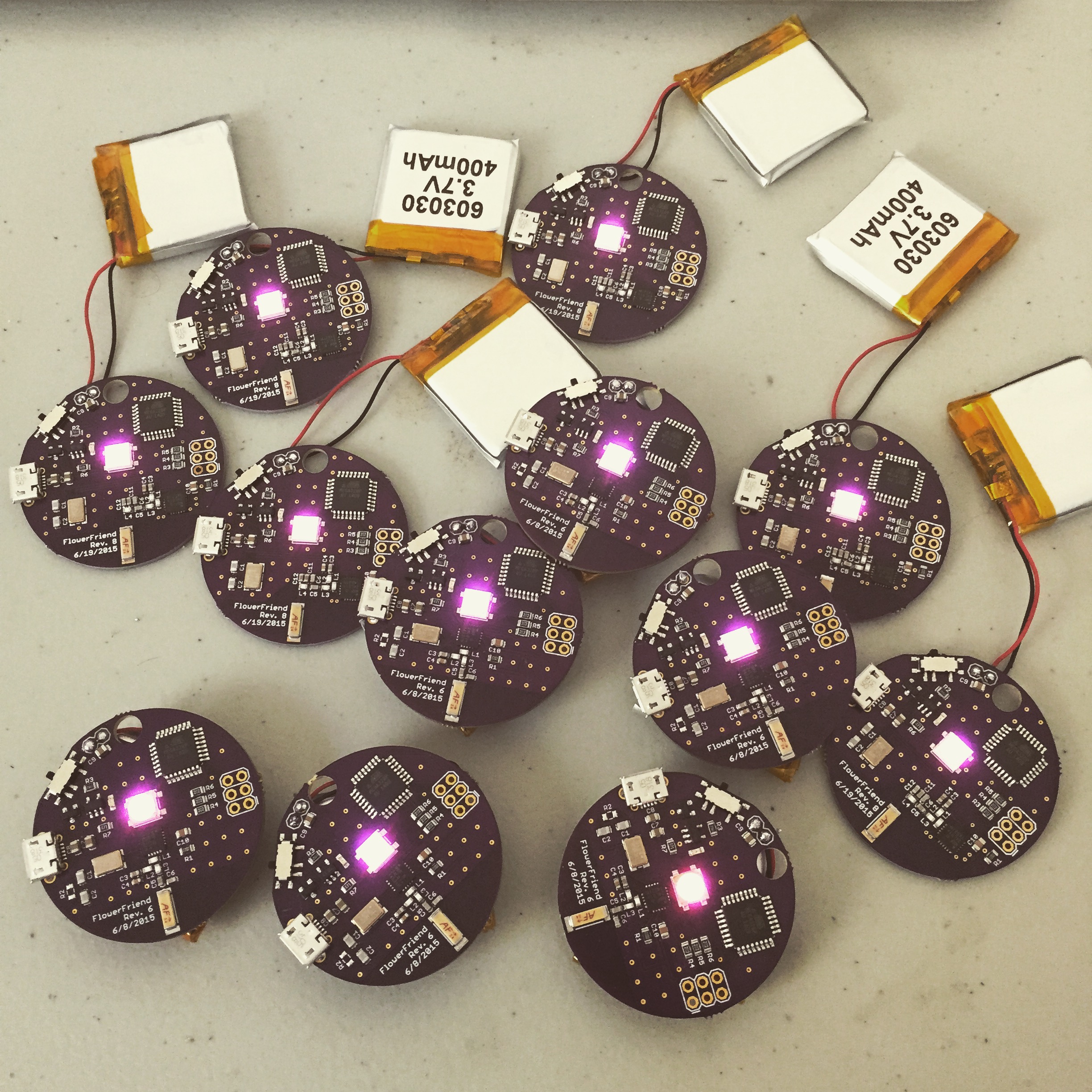
  • Generic 400 mAh Lithium Polymer Battery

I went with the ATmega328P, NRF24L01+, and WS2812B because they are really common, are well supported with software and documentation, and I was already familar with them.

Schematic of Revision 8 PCB

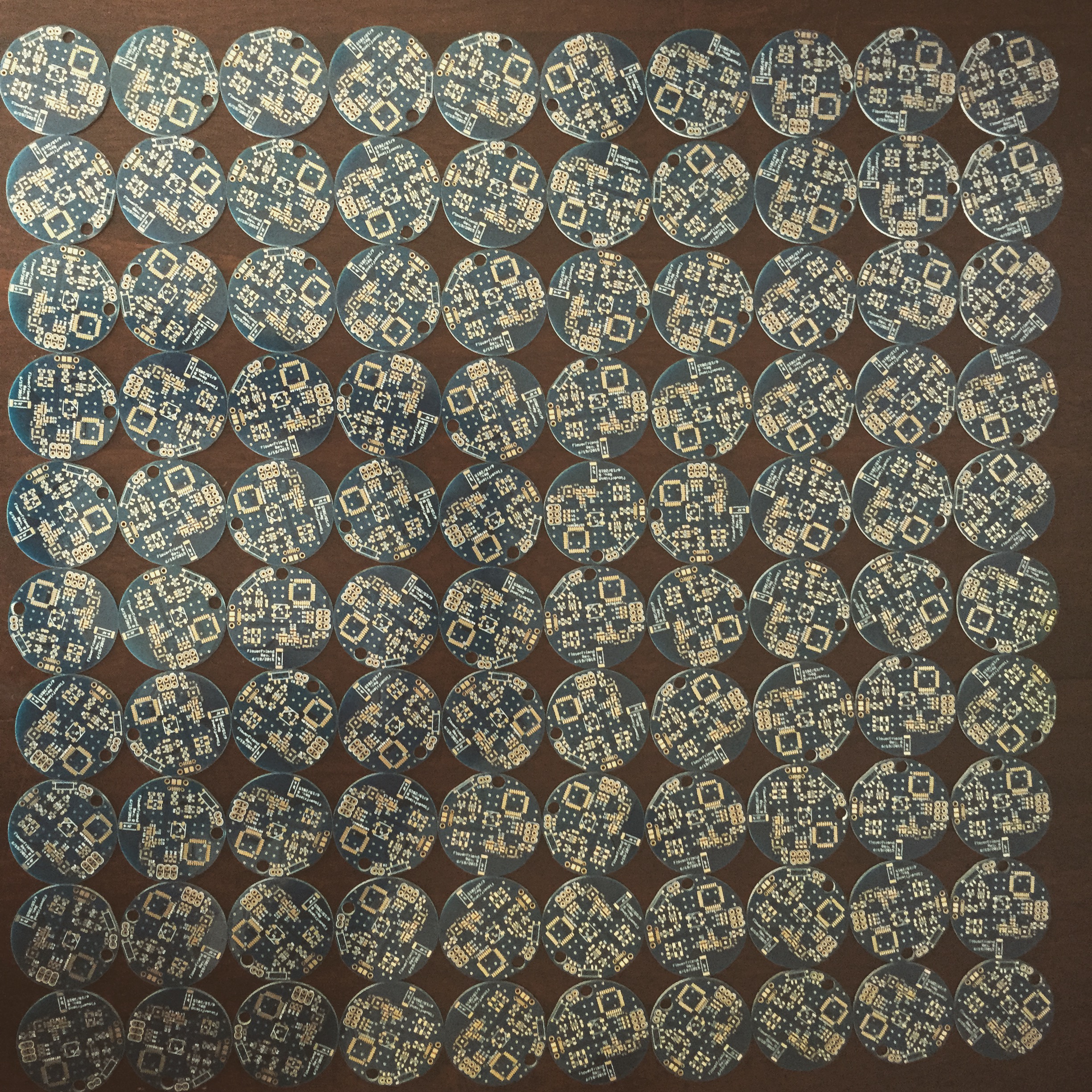
The boards were layed out into an approximately 4 cm circle in order to exactly fit a square 400 mAh battery on the back, and a glued-on fabric flower on the front.

Revision 8 Board Layout

A gaggle of functional PCBs powered on and syncing

Custom PCBs syncing

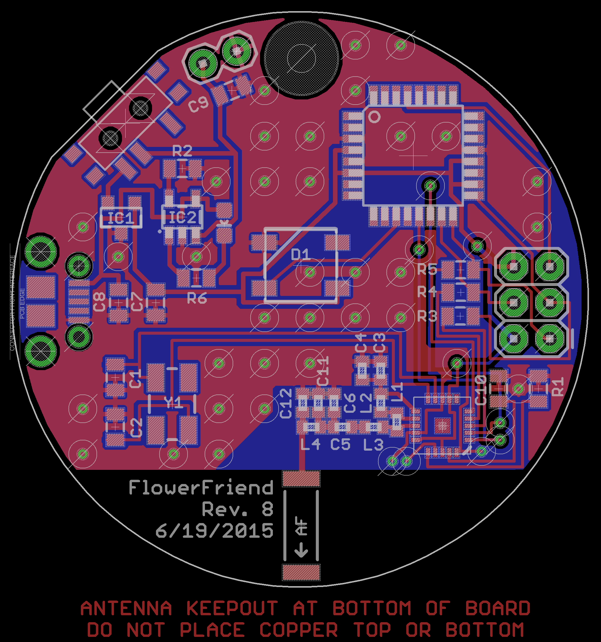
Optimizing the NRF24L01+ Matching Network

Most of the design considerations came from rolling my own RF circuit rather than using an FCC approved module ($$). Having never designed an RF board before, it quickly became apparent that getting it to work up to spec was going to be a challenge. Initial prototypes worked in the range of inches rather than the 150+ feet reported with commercial modules.

After a few non-working revisions and a productive discussion with a Nordic employee, I was able to increase range to 150 feet, at night, with line-of-sight. This was accomplished by: 1) removing the top ground plane surrounding the RF front-end, 2) increasing the number of vias connecting the top and bottom ground planes, and most importantly, 3) adding a few components to bring the impedance of the matching network to the 50+0j ohms expected by the chip antenna.

To optimize the matching network, you need access to a network analyzer. This fantastic piece of equipment simultaneously generates signals across a frequency range, pumps them through your DUT (device under test), and measures both the magnitude AND phase of the signal either transmitted through the DUT (two-port measurement) or reflected back toward the input (single-port measurement). It is important that the network analyzer can determine the phase of the signal because this allows it to calculate the complex impedance of the matching network. If the signal at 2.45 GHz output by the NRF24L01+ reaches the chip antenna at an impedance other than 50 ohms, some amount of the signal is reflected back through the matching network and is lost, resulting in a severe decrease in power output, and therefore, range.

Step One: Solder an SMA cable to the 50 ohm matching point and ground plane

Step Two: Measure initial impedances using a network analyzer

Step Three: After soldering matching components to board, measure impedances again

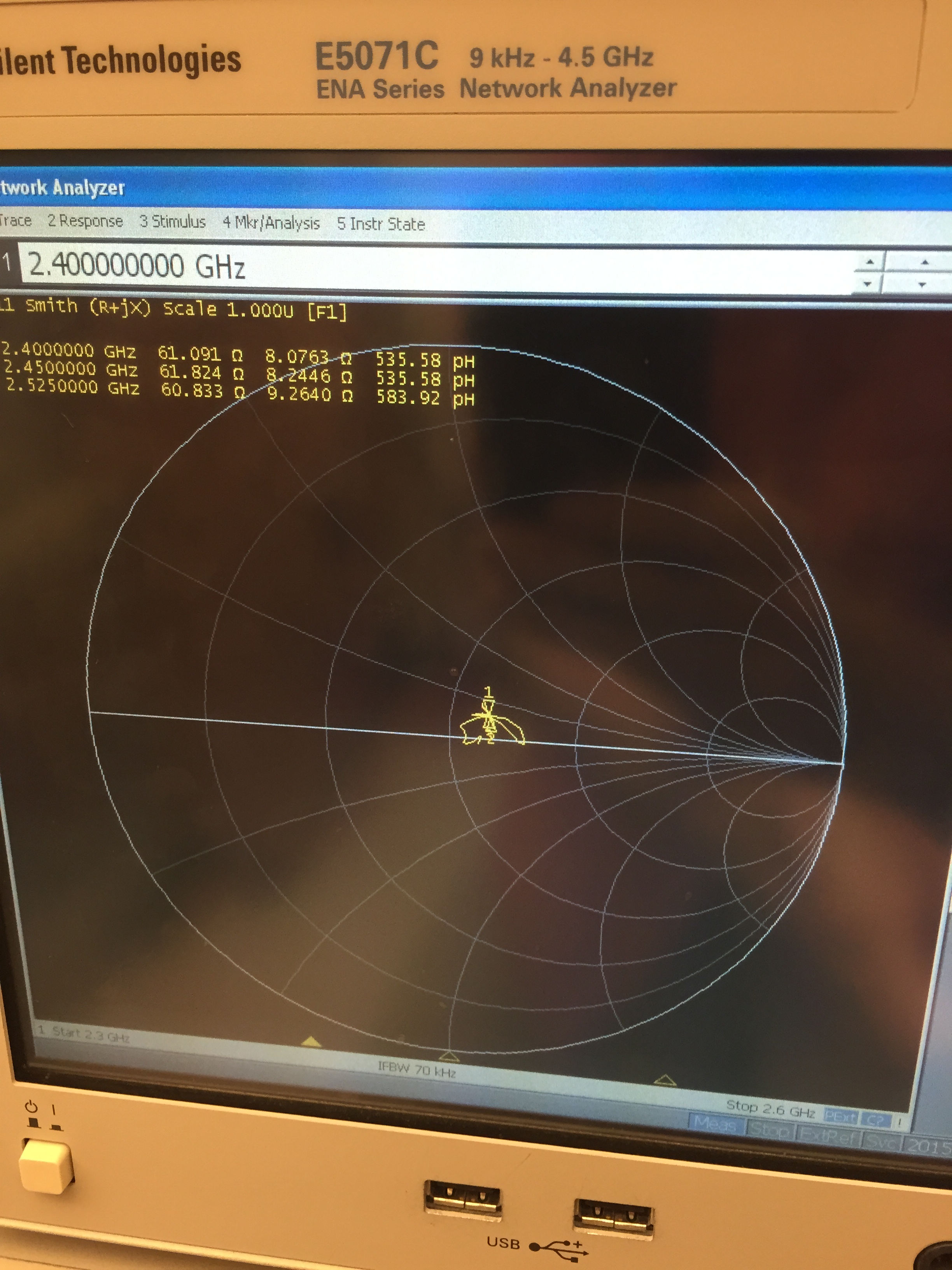
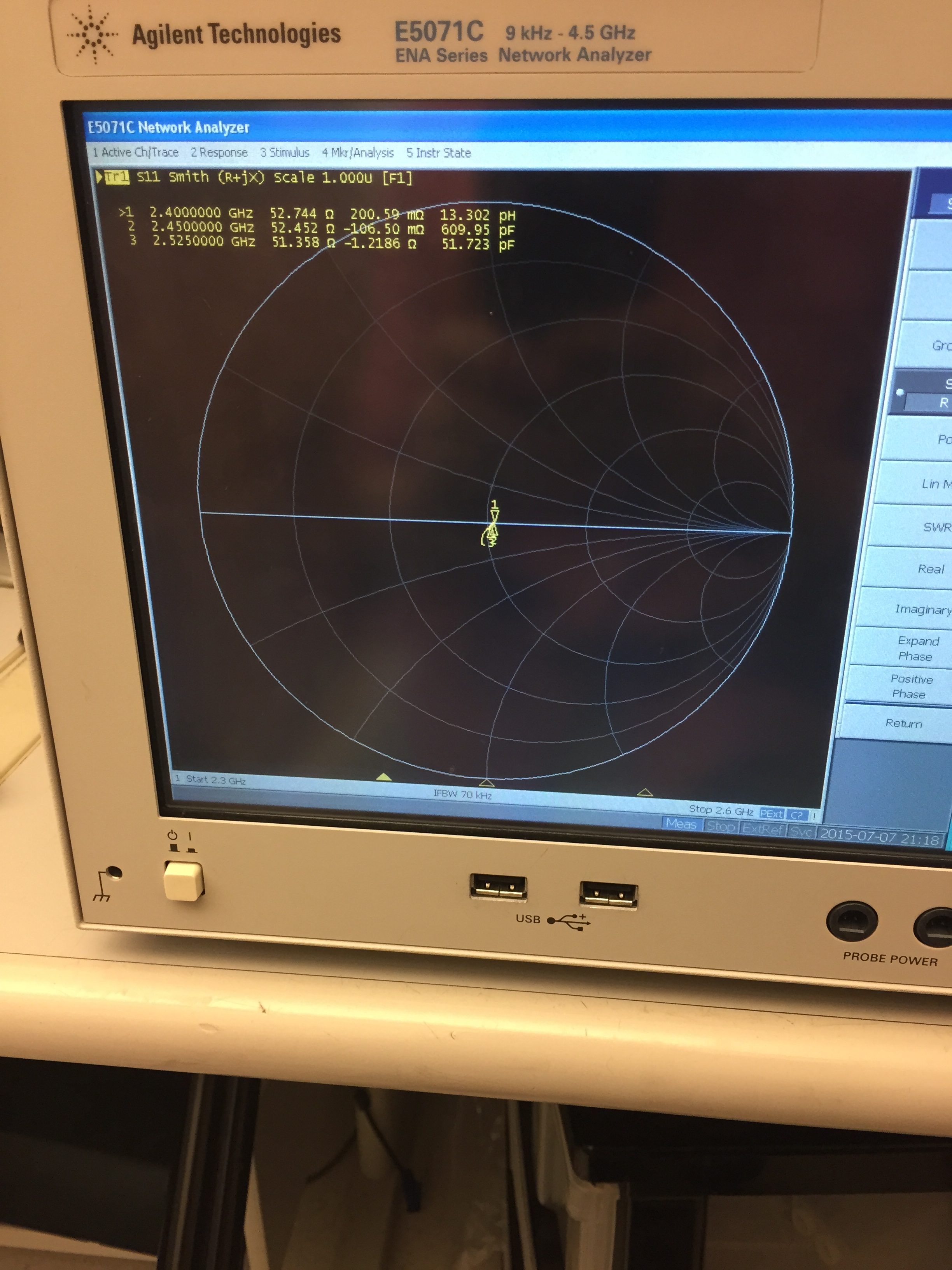
After adding a series 1.5 nH inductor and shunt 0.5 pF capacitor, the impedance was pretty much 50+0j ohms, in spec for the 2.45 GHz chip antenna I used.

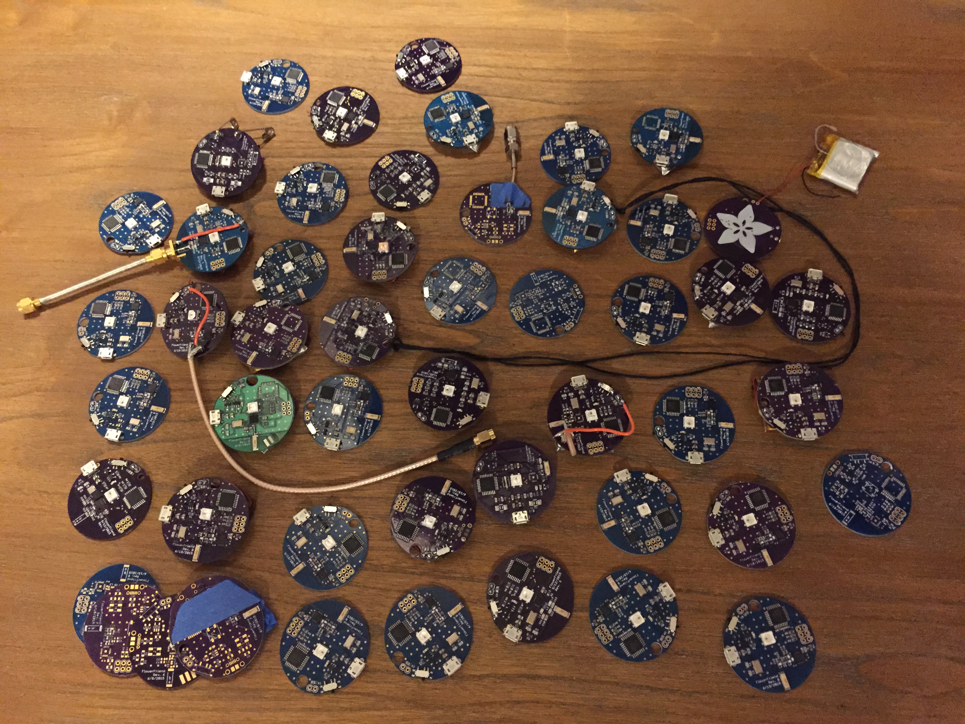
Reproducibly hand-assembling tiny components

Once the design was finalized, I was faced with the daunting and tedious task of hand-assembling 100 units. Automated assembly was quoted at something like $5-10 per unit, which was just a little too expensive.

One hundred empty boards waiting for assembly

In retrospect, it would have been worth it. It's just not reasonable to place thousands of these tiny surface mount components by hand and expect to have most of the units work. I wound up tossing around 35 of them due to shorts or crappy range (less than 70 feet). That said, it is possible to do pretty well by using a real, metal stencil, a good solder paste, and being careful. Getting the right amount of solder paste on the QFN package was the tricky part: too little and some pins weren't connected, too much and there were bridges that, if fixed with an iron, often ruined the chip.

As many boards as I brought to Burning Man, I wasted on failed prototypes

Software


Design Overview

The primary function of the flowers is to transmit their presence to other flowers within range of the built-in 2.4 GHz radio. Secondary to this is their ability to transmit a clock value and synchronize color patterns to each other. To accomplish this, every flower maintains a list of colors that it has received, keeps a clock value which it synchronizes to the lowest color value flower in the network, transmits its own color at a regular interval, and retransmits all packets it receives to form a mesh topology network.

All code is available on GitHub here. I tried to keep it pretty well commented, but I'm also describing some more important stuff below.

Staying in sync

The main issue with keeping units in sync came from a variable amount of work being done on each loop() iteration: units doing more stuff on each loop inevitably fell behind and had to "catch up" to units doing less stuff. This was an easy fix: by using a timer to force each iteration to take 20 ms (far longer than the amount of stuff being done by any one unit), sync was more easily achieved.

More complex issues came from the fact that packets were often received several iterations after they were sent out, resulting in an effect where units sync'd their clocks to "stale" clock values. This was a result of the NRF24L01+ keeping packets in a FIFO queue received one per iteration, and mesh network packets making it to the edge of the network several iterations late. Some code to discard duplicate packets (including very old ones), and adjust clock values in packets based on how long ago we guessed they were sent, helped a lot.

Ultimately, syncing worked reasonably well--very well according to those less OCD than me. I think the fading color pattern helped obscure that fact that the clocks weren't exactly together.

Maximizing range of the NRF24L01+

The single most important factor, I found, in increasing the range of the radio came from decreasing the packet size to 8 bytes. If we consider that every bit in a packet has an equal probability of being misreceived (i.e. skipped, or considered a 1 when actually a 0), the longer the message, the higher cumulative probability of an error occuring. If the packet checksum fails, the entire message is thrown out. It seems like a safe assumption that at distances where power of the signal being received is close to the sensitivity of the radio (-94 dBm @ 250 kbps), there is a higher probability of receiving a fucked up packet made even higher by using a longer length.

The next most important factor was decreasing the transmission speed to 250 kbps. The NRF24L01+ can transmit at speeds up to 2 Mbps, but I found that the range dramatically decreased at that rate, in concordance was a sensitivity of -82 dBm at 2 Mbps versus -94 dBm at 250 kbps. Considering the simplicity and low data rate required by this application, it didn't make much sense to use anything above the minimum speed of 250 kbps.

Finally, I decided to send every packet out three times per transmission, reasoning that at least one of them would get through. This seemed to help a lot with range.